Awe-Inspiring Examples Of Tips About What Is LCR And RLC Circuit

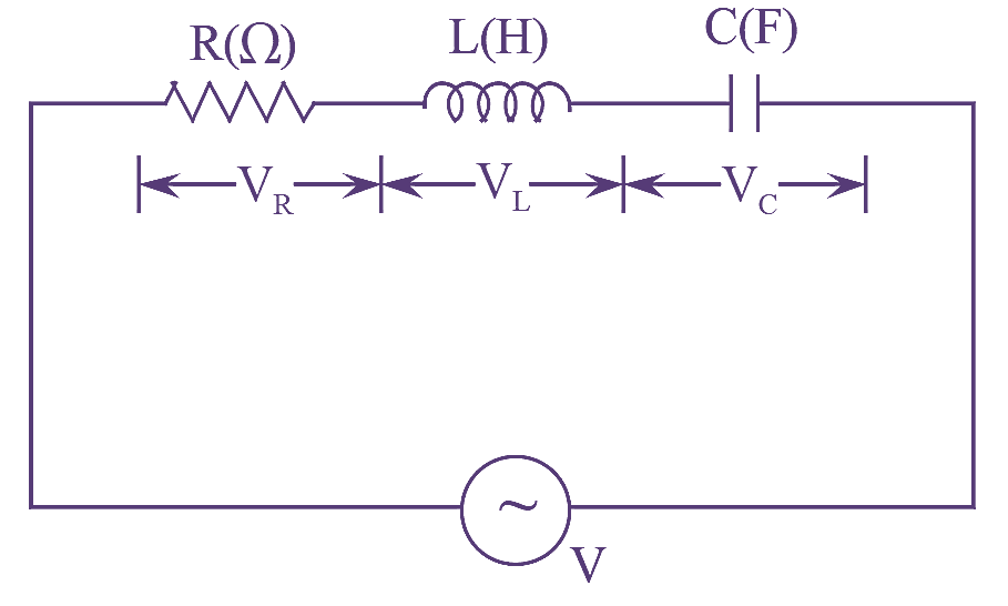
How To Draw A Phasor Diagram For Rlc Circuit Combined Ci
Decoding LCR and RLC Circuits
1. What are these circuits anyway?
Alright, let's tackle those cryptic letters: L, C, and R. They stand for Inductor (L), Capacitor (C), and Resistor (R), the fundamental building blocks of many electronic circuits. An LCR circuit, or an RLC circuit, as it's sometimes called, is simply a circuit that contains all three of these components. The order "LCR" or "RLC" doesn't usually matter for basic functionality; it's more about convention or emphasis in certain analysis contexts.
Think of it like this: a resistor is like a narrow pipe restricting the flow of water (electricity). An inductor is like a spinning flywheel that resists changes in flow (current). And a capacitor? That's like a water tank that stores water (charge) and releases it later. Combine all three, and you've got a recipe for some interesting electrical behavior!
These circuits are incredibly common. You'll find them in everything from radio tuners and filters to power supplies and oscillators. They're used to filter out unwanted frequencies, create specific signal timings, or store energy. They really are the unsung heroes of the electronic world.
So, why bother learning about them? Well, understanding how LCR and RLC circuits work is essential for anyone dabbling in electronics. It allows you to design and troubleshoot circuits, understand their behavior, and harness their capabilities for various applications. Plus, it's just plain cool to know how things work under the hood!

Resistors, Inductors, and Capacitors, Oh My! A Closer Look
2. Understanding the Components
Let's break down each component a little further. Resistors, measured in Ohms (), are the simplest. They impede the flow of current, converting electrical energy into heat. Theyre like the friction brakes of your electricity car. Higher resistance means less current flow for a given voltage.
Inductors, measured in Henries (H), store energy in a magnetic field when current flows through them. They resist changes in current. Picture them as energy reservoirs that smooth out current fluctuations. When the current tries to increase rapidly, the inductor opposes it, and vice-versa. This makes them useful for filtering and energy storage.
Capacitors, measured in Farads (F), store energy in an electric field. They resist changes in voltage. Think of them as tiny rechargeable batteries. They charge up when voltage is applied and discharge when the voltage drops. Capacitors are key for filtering, smoothing voltage, and timing circuits.
The interaction between these three components is what makes LCR and RLC circuits so versatile. Each component responds differently to alternating current (AC) signals. This differential response is then harnessed by circuit designs to create filters or to tune to a specific frequency.

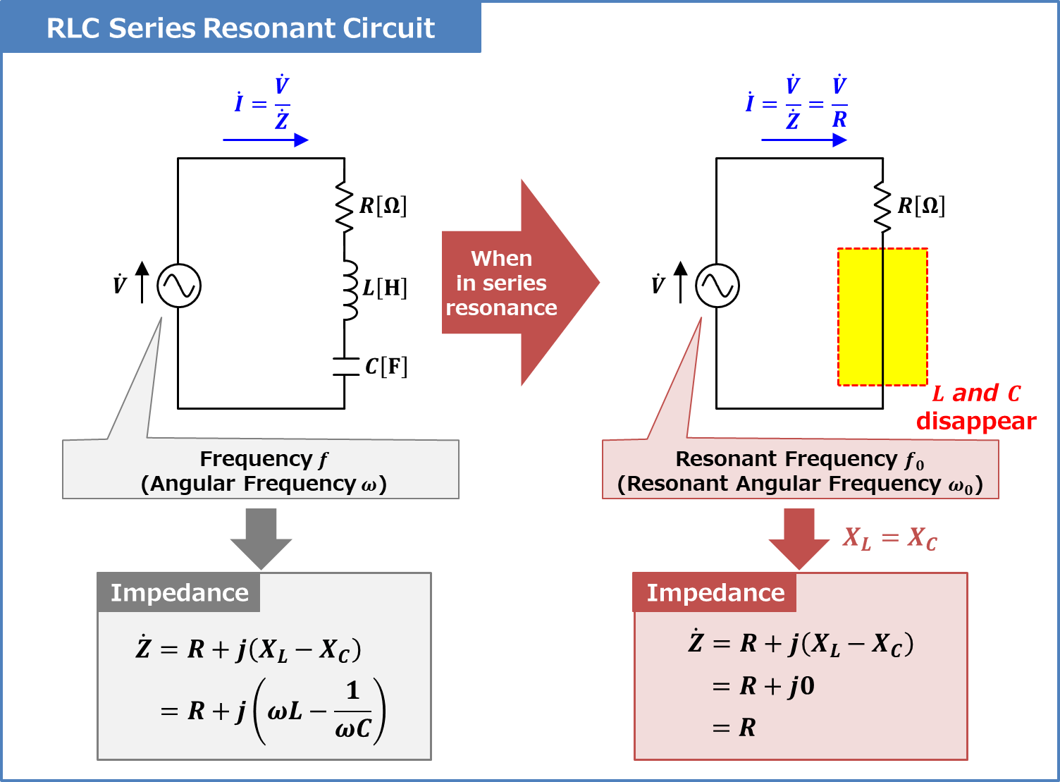
Resonant Frequency In Lcr Circuit At Ida Barrera Blog
Resonance
3. The Magic of Tuning
Heres where things get interesting: resonance. In an LCR circuit, the inductor and capacitor store energy, swapping it back and forth between their magnetic and electric fields. At a specific frequency, called the resonant frequency, the inductor and capacitor effectively cancel each other out. This results in maximum current flow through the circuit (or minimum impedance, depending on how it's configured).
Imagine pushing a child on a swing. If you push at the right frequency (the natural frequency of the swing), the child will swing higher and higher. The resonant frequency of an RLC circuit is like that natural frequency for the electrical signals. It's determined by the values of the inductor and capacitor.
This resonance phenomenon is used in countless applications, especially in radio receivers and transmitters. By tuning the resonant frequency of an LCR circuit, you can selectively amplify signals at that frequency, filtering out unwanted noise and interference. That's how your radio picks up your favorite station!
Off resonance, the impedance of the LCR circuit increases, reducing the current flow. This property makes LCR circuits very useful for building bandpass or band-stop filters. So, whether you want to let certain frequencies through or block others, the LCR circuit is your trusty tool.

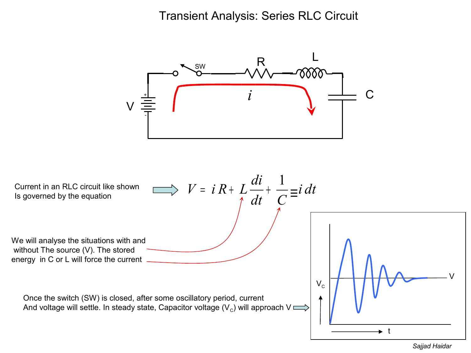
What Is Series Lcr Circuit Diagram
Series vs. Parallel LCR/RLC Circuits
4. Different Arrangements, Different Behaviors
LCR and RLC circuits can be arranged in two main configurations: series and parallel. In a series LCR circuit, the resistor, inductor, and capacitor are connected one after the other, forming a single path for current flow. In a parallel LCR circuit, the components are connected side-by-side, providing multiple paths for current.The behavior of the circuit is significantly affected by its configuration. In a series LCR circuit at resonance, the impedance is at its minimum, and the current is at its maximum. In a parallel LCR circuit at resonance, the impedance is at its maximum, and the current is at its minimum (through the source). The voltage across the inductor and capacitor can be much larger than the source voltage in a series resonant circuit.
Choosing between a series or parallel configuration depends on the specific application. Series circuits are often used when you want to amplify a specific frequency signal, while parallel circuits are used when you want to reject a specific frequency. The choice depends on whether you need impedance minimized or maximized at the resonant frequency.
Understanding the differences between series and parallel LCR and RLC circuits is crucial for designing effective filters and resonant circuits. Each configuration offers unique advantages and disadvantages, and the optimal choice depends on the desired performance characteristics.

Lcr Circuit Phase Diagram
Practical Applications of LCR/RLC Circuits
5. Where are they used in real life?
Okay, so we've covered the theory. But where do LCR and RLC circuits actually show up in the real world? Well, pretty much everywhere! They're the backbone of countless electronic devices and systems.
Think of your radio or TV. The tuning circuit that selects the channel you want to listen to or watch is almost certainly an LCR circuit. It's carefully tuned to resonate at the frequency of the desired signal, filtering out all the other noise and interference.
Power supplies also rely heavily on LCR circuits. They are used to filter out noise and ripple from the AC line voltage, providing a clean and stable DC voltage to power your electronic devices. Without them, your devices would be susceptible to damage and malfunction.
Even in more complex systems like medical equipment and industrial control systems, LCR and RLC circuits play a vital role. They're used for signal processing, filtering, and timing functions, ensuring the accurate and reliable operation of these critical systems. So, the next time you use your phone or turn on your computer, remember that these unassuming little circuits are working hard behind the scenes.

Troubleshooting LCR/RLC Circuits
6. What if it's not working right?
So, you've built your LCR circuit, and it's not behaving as expected. Don't panic! Here are a few tips to help you troubleshoot the problem. First, double-check your wiring. Make sure all the components are connected correctly and that there are no shorts or open circuits. A simple visual inspection can often reveal the culprit.
Next, verify the values of your components. Resistors can be easily checked with a multimeter, but inductors and capacitors may require specialized testers. Make sure you're using components with the correct values and tolerances. Sometimes, a seemingly small difference can have a significant impact on the circuit's performance. Think of a slightly too long or short pipe in your water system that can change the whole performance.
Also, consider the signal source. Is it providing the correct frequency and amplitude? Try varying the input signal to see how the circuit responds. This can help you identify any issues with the signal source or the circuit's response to different frequencies. Check for source impedance, too, because the circuit might respond to the source impedance value.
Finally, use an oscilloscope to observe the voltage and current waveforms in the circuit. This can provide valuable insights into the circuit's behavior and help you identify any oscillations, distortions, or other anomalies. Troubleshooting LCR and RLC circuits can be challenging, but with a systematic approach and a little patience, you can usually track down the problem.